P
Learn about Panorama, Pose, Primitives, and other setting categories starting with P in Clip Studio Paint.
Panorama
You can set up a panorama when a 3D layer is selected with the Object tool.
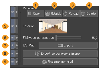
(1)File
In the Open dialog that appears, you can select a file to import as a panorama. You can import the following image file formats: Clip Studio format (extension: clip), BMP, JPEG, PNG, TIFF, Targa, Adobe Photoshop Document (extension: psd), and Adobe Photoshop Big Document format (extension: psb).
(2)Materials
In the Add a texture dialog that appears, you can import a panorama material from the Material palette. For details on the Add a texture dialog, see "Adjusting panorama materials".
(3)Reload
When an external file is used as the panorama, you can update the image to reflect any changes to the original file, based on the stored file path.
(4)Delete
Deletes the panorama texture from the 3D layer.
(5)Texture
A thumbnail of the current panorama texture. You can tap the thumbnail to open the dialog and select a different file to import as a panorama.
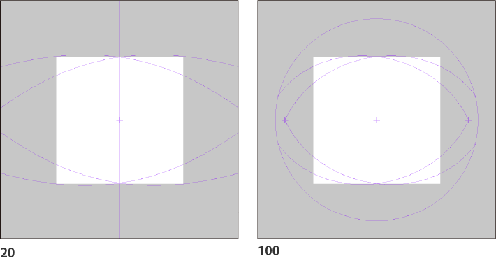
(6)Fish-eye perspective
You can apply fish-eye distortion to only to the panorama. The larger the number, the wider the angle of the panorama shown on the canvas. However, distortion may occur at the edges.
(7)Rotation angle
You can change the rotation angle of the panorama. See "Adjusting panorama materials" for details.
(8)Export
You can export the image as a UV map in Clip Studio format (extension: clip).
The exported UV map is divided into a “map” layer with grid lines, a “texture" layer with the texture image, and a “background color" layer filled with white. All are raster layers.
(9)Export as panorama image
The exported panorama image is divided into a “map” layer with grid lines, a “panorama" layer with the panorama image of the 3D layers, and a “background color" layer filled with white. The “panorama" layer is transparent in parts that don’t have a 3D object on the canvas.
(10)Register material
You can save an imported panorama to the Material palette. The Material property dialog will open, where you can check the settings.
Perspective ruler
You can adjust settings for using the Perspective ruler tool.
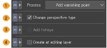
(1)Process
Select how to edit with the Perspective ruler tool.
Add vanishing point | Adds a vanishing point to the perspective ruler. If there is no perspective ruler, this creates a new one. |
Delete vanishing point | Deletes a vanishing point from the perspective ruler. |
Add guide | Adds a guide to the perspective ruler. |
Delete guide | Deletes a guide from the perspective ruler. |
Fix vanishing point | Fix the position of a vanishing point on the perspective ruler. |
Infinitize | Sets a vanishing point of the perspective ruler to infinity. |
(2)Change perspective type
When turned off, you can add an auxiliary vanishing point without changing the perspective drawing method. When turned on, adding a vanishing point to an existing perspective ruler changes the perspective drawing method. For example, you can change a two-point perspective ruler to a three-point perspective ruler. For details, see "Perspective Rulers".
(3)Add fisheye
Turn this on to create a fisheye perspective ruler. For details, see "Creating a fisheye perspective ruler".
(4)Create at editing layer
When turned on, the perspective ruler is created on the current layer. When turned off, a new raster layer is created when you make a new ruler.
When using the Object tool
When the perspective ruler is selected with the Object tool, you can set how to snap and show the ruler.
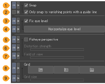
(1)Snap
When turned on, you can snap drawing tools to a perspective ruler. When another special ruler is displayed on the same canvas, you cannot snap to other special rulers. You can do the same operation by enabling snapping.
(2)Only snap to vanishing points with a guide line
When on, drawing tools will not snap to vanishing points without a guide line or to the lens center of a fisheye perspective ruler.
(3)Fix eye level
Configures the eye level operation. When turned on, the vanishing point moves along the eye level. When turned off, the position of the eye level moves in conjunction with the vanishing point.
(4)Horizontalize eye level
Tap the perspective ruler to make the eye level horizontal.
(5)Fisheye perspective
Turn this on to switch to a fisheye perspective ruler. For details, see "Converting to a fisheye perspective ruler".
(6)Distortion strength
The larger the value, the stronger the fisheye distortion. If you set the Distortion Strength to 0, the ruler will appear like a normal perspective ruler. When set to 1 or higher, the perspective ruler will be distorted and the field of view (lens circle) will appear.
(7)Field of view
Changes the size of the lens circle and the entire fisheye perspective ruler.
(8)Grid
Displays an equally-spaced grid (auxiliary lines) from the vanishing point.
(9)Grid size
You can adjust the space between grid lines.
Memo | If you adjust the Distortion strength or Field of view while a vanishing point is selected, you can change the distortion and size of the fisheye perspective ruler without moving the selected vanishing point. |
Pinch line
Allows you to configure how a line is pinched when a vector layer or balloon layer is selected with the Pinch Vector Line tool.
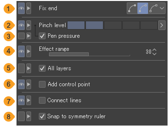
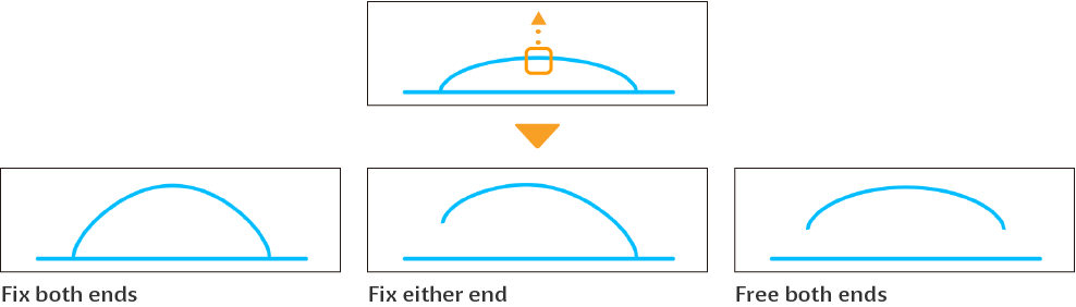
(1)Fix end
Allows you to select whether or not and how to fix (lock) the start point or end point when transforming a line.Fix both ends fixes the start and end points of the line, so they will not move even if the line is pinched.Fix either end fixes the further end from where the line is being pinched. The fixed end will not move even if the line is pinched.Free both ends does not fix any ends. The start and end point can both move.
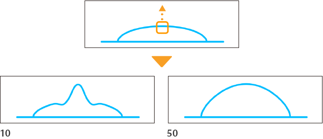
(2)Pinch level
You can set the range of the effect when applied to the line. When the value is small, a small area of the line is affected. When the value is large, the entire line can be transformed.
(3)Pen pressure
When turned on, pen pressure affects the Pinch level setting.
(4)Effect range
You can set the range to apply the effect. The higher the number, the wider the range over which the effect is applied.
(5)All layers
When turned on, the selected process can be applied to vector layers, balloon layers, frame border folders, and drawn lines on rulers on the canvas. Tap the line you wish to edit to switch to that layer.
(6)Add control point
When turned on, you can add control points when pinching the line. Adding control points makes the line smoother after transforming.
When turned off, control points are not added, so the line may appear distorted after the transformation. However, this setting is useful when you want to transform straight lines.
(7)Connect lines
When turned on, you can connect two neighboring segments with the same settings for pen tip shape, angle, color and so on. You can drag to overlap the ends of both segments when pinching a line in order to connect the two segments.
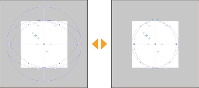
(8)Snap to symmetry ruler
When turned on, the Pinch vector line tool will snap to symmetry rulers.
Pose
You can adjust the pose of a 3D head model or a 3D hand model. The settings shown here will vary depending on the material you select.
Pose settings when a 3D drawing figure is selected
When a 3D drawing figure or 3D character material is selected with the Object tool or other tools, you can set its pose and register it as a pose material.
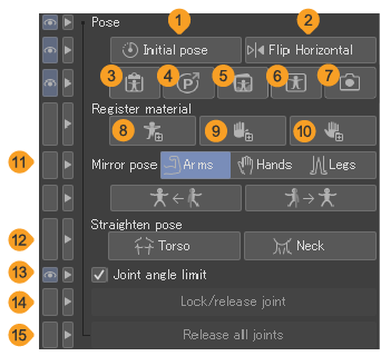
(1)Initial pose
Tap to return the 3D drawing figure or 3D character material to the default pose.
(2)Flip horizontal
Tap this to flip the pose of a 3D drawing figure or 3D character material horizontally.
(3)Use 3D pose materials
For details, see "Importing pose materials".
(4)Posemaniacs
For details, see "Using POSEMANIACS poses".
(5)Pose Scanner (Technology preview)/Pose Scanner (image)
For details on importing poses from photos with Pose Scanner, see "Pose Scanner".
(6)Pose Scanner (camera) (Tablet)
For details on importing poses from photos with Pose Scanner, see "Pose Scanner".
(7)Pose Scanner (photo library) (iPad)/Pose Scanner (storage) (Android)
For details on importing poses from photos with Pose Scanner, see "Pose Scanner".
(8)Register full body pose as material
For details, see "Swapping 3D drawing figures and 3D character materials".
(9)Register left hand pose as material
For details, see "Swapping 3D drawing figures and 3D character materials".
(10)Register right hand pose as material
For details, see "Swapping 3D drawing figures and 3D character materials".
(11)Mirror pose
For details, see "Making a pose symmetrical".
(12)Straighten pose
For details, see "Straightening a pose".
(13)Joint angle limit
For details on the joint angle limit, see "Posing body parts".
(14)Lock/release joint
For details, see "Locking and releasing joints".
(15)Release all joints
For details, see "Locking and releasing joints".
Memo | About the Pose Scanner ·The Pose Scanner is a technology preview function. You can try it out before its official release. ·When you use this feature, the image data is uploaded to the server, where the AI interprets the data and estimates the pose. A network connection is necessary to use this function. For information on images uploaded to the server and generated data, see "About AI features". ·If you choose an image with multiple figures in it, the pose of the largest full-body figure will be applied. Figures may not be recognized depending on the photo used. ·The Pose Scanner cannot apply hand poses including fingertip positions to 3D drawing figures or 3D character materials. |
Memo | You cannot register pose materials in Clip Studio Paint DEBUT. |
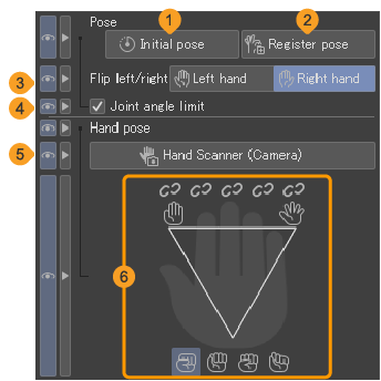
Pose settings when a 3D hand model is selected
When a 3D hand model is selected with the Object tool or other tools, you can set its pose and register it as a pose material.
 mp
mp
(1)Initial pose
Tap to reset the 3D hand model back to its original default pose.
(2)Register pose
See "Registering hand pose materials".
(3)Flip left/right
You can switch the 3D hand model between the right hand and left hand. The shape and pose of the hand will not change.
(4)Joint angle limit
When turned on, the joint range of the hand will be limited when dragging parts of the 3D hand model with a pen or mouse in gimbal mode, making it move more like real human joints.
(5)Hand Scanner
Tap to launch the "Hand Scanner" to pose the hands using the camera feed.
(6)Hand setup
Use this to pose the hands and fingers. For details, see "Adjusting the hand pose".
Pose sequence
You can adjust how pose materials are applied to a 3D model selected with the Object tool.
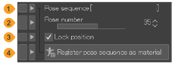
(1)Pose sequence name
The name of the pose sequence is shown here. If you import a BVH motion file, the file name will be shown.
(2)Pose number
Use the indicator bar or the numerical input to change the pose within the sequence.
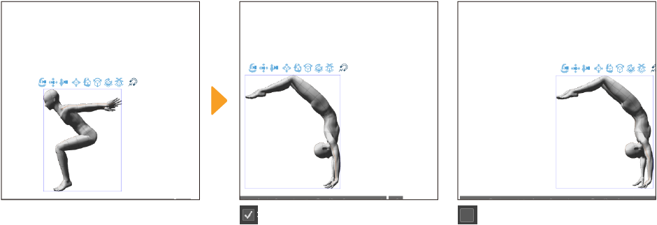
(3)Lock position
When turned on, the model will remain in the same position when you change the pose. When turned off, the position will move according to the pose data.
(4)Register pose sequence as material
Tap to open the dialog to register the pose sequence as a material in Clip Studio Paint.
Preferences
You can set how 3D layers appear when selected with the Object tool.
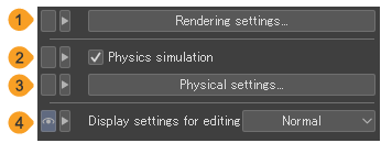
(1)Rendering settings
Tap the open the Rendering settings dialog where you can configure settings such as outlines and lighting (light sources) for 3D materials.
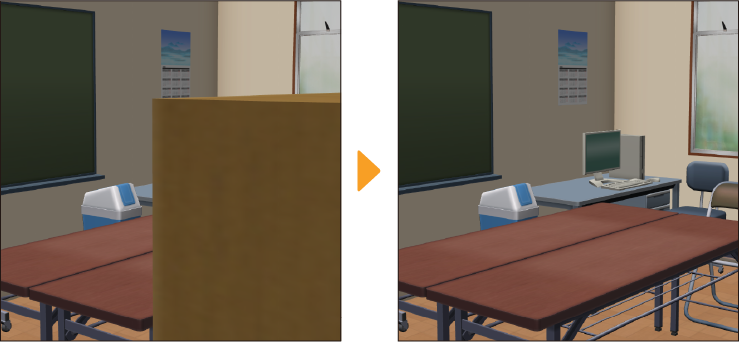
(2)Physics simulation
Enables/disables physics for 3D character materials. When turned on, moving the 3D character causes the hair and skirt to move according to the physics settings.
The Physics simulation option shows when a 3D character material with physics settings from Clip Studio Modeler is selected.
Memo | ·For information on Clip Studio Modeler, see https://www.clipstudio.net/en/modeler/. ·Importing a 3D character material with physics settings may slow Clip Studio Paint. Turning off Physics simulation may improve the processing speed. |
(3)Physical settings
Select this to show the Physics settings dialog and set how the physics operation will be shown on the 3D character.
(4)Display settings for editing
Select Normal or Fast to change the display settings for editing a 3D layer.
Fast makes 3D layers display more smoothly. When using a 3D layer, the effects from the Layer Properties and Layer palettes will not show. Also, you will not be able to show the full view of the canvas in the Navigator palette.
When you finish editing the 3D layer and switch to a different layer, it will return to its original appearance.
(5)Shadow resolution
Set the resolution of shadows cast on the 3D layer. Setting Shadow resolution to High makes the edges of the shadows look sharp and crisp. Lowering the resolution makes the edges blurrier, but it helps the 3D layer run faster and more smoothly.
(6)Manipulator
When turned on, this displays the Manipulator for a part of a 3D character compatible with Version 1.5. Drag the Manipulator to pose a 3D character material or change the angle of a 3D object material.
Hover over each ring and drag to rotate the part selected in the direction of the ring.
Rendering settings

Outline
The Outline settings relate to the outline of the 3D material.
(1)Add outline
Turn this on to add an outline to the 3D material.
(2)Width
Sets the width of the outline. The larger the value, the thicker the outline.
(3)Opacity
Sets the opacity of the outline.
(4)Offset amount
You can set how much the outline will be offset from the 3D material polygon. Changing this value changes whether or not an outline embedded in other polygons is displayed.
(5)Color
Sets the color of the outline. Tap the color icon to open the "Color Settings dialog".
Lighting
The Lighting settings relate to the lighting of the selected 3D material.
(6)Apply light source
Turn this on to apply a light source on the selected 3D material. It is linked with the same setting under "Light Source". For details on the light source, see "Light Source".
If you have Apply light source in 3D layer settings turned off, you will not be able to select this option.
(7)Method
You can select a method for applying shadows to the selected 3D material: Gouraud, Phong, or Toon.
Gouraud creates smooth shadows.Phong creates smoother shadows than Gouraud. However, depending on your device, the 3D material display may slow down operation.Toon creates simplified gradient shadows.
If a 3D object that supports photorealism is selected, this setting is locked as Realistic and other options cannot be selected.
(8)Cast shadows
When turned on, the object casts shadows in the 3D space. This setting is linked with the setting of the same name in the "Light Source" category.
Texture
The Texture settings affect how texture is displayed on the selected 3D material.
(9)Use texture
You can show or hide the texture on the selected 3D material. You cannot do this if there is no texture set.
(10)Alpha test
You can set the opacity threshold for extracting texture line art from the selected 3D material. For example, if Alpha test is set to 0.5, then lines will not be extracted from a texture with Opacity set below 50%.
Backface culling
Turn this on to enable backface culling. The back faces of polygon drawings are omitted.
Clipping planes
A clipping plane is an imaginary plane that follows the camera's viewpoint. There are two types of planes: near planes and far planes. These add effects to the entire 3D layer.
(11)Set automatically when resetting camera
When turned on, this automatically applies Near plane and Far plane settings when the camera position is reset, such as with Focus on editing target in the Object Launcher.
(12)Near plane
Set the distance for the near plane. Faces (polygons) cannot be drawn closer than this plane. You can use this to hide parts in the foreground.
(13)Far plane
You can set the position of the far plane. Faces (polygons) cannot be drawn further away than this plane.
Lighting
You can set up the light source for the entire 3D layer.
(14)Apply light source
Turn this on to apply the light source to the entire 3D layer. For details on the light source settings, see "Shadow settings for new 3D layers".
(15)Shadow settings
You can choose Cast shadows down, or Follow light source when displaying shadows on a 3D layer.Cast shadows down displays shadows perpendicular to the floor.Follow light source displays shadows according to the direction of the light source. For more details, see "Shadow settings for new 3D layers".
(16)Rendering method
You can select the 3D layer rendering method from Normal, Ver. 1.12.3 or earlier, or Ver. 1.11.4 or earlier.
(17)Apply to all models
The Rendering settings dialog settings will be applied to all 3D layers on the canvas.
Physical settings
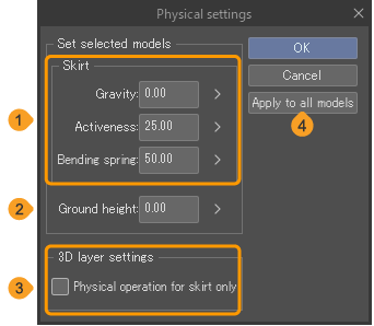
(1)Skirt
Control the movement of the skirt on a 3D character that has had the rigid body of the skirt configured in Clip Studio Modeler. For information on Clip Studio Modeler, see here.
·Gravity: Set how much gravity will affect the skirt movement. The larger the value, the greater the effect of gravity.
·Activeness: Set how exaggerated the skirt movement will be. The larger the value, the greater the movements of the skirt when the character moves.
·Bending spring: Set how easily the skirt bends. The larger the value, the harder it will be for the skirt to bend when the character moves.
(2)Ground height
Set the length at which the skirt will start to bend when reaching the ground. The skirt will not fall lower than Ground height as long as the position of the character's hips is higher than Ground height.
(3)Physical operation for skirt only
Sets how physics operation will be applied to the whole of the 3D layer when a 3D character material is controlled. You can apply physics operations to just the skirt.Other physics operations are not reflected in Clip Studio Paint.
(4)Apply to all models
Applies the settings in the Physics settings dialog to 3D character materials on all 3D layers in the canvas.
Primitives
You can adjust the number of faces and size of textures applied to primitives selected with the Object tool.
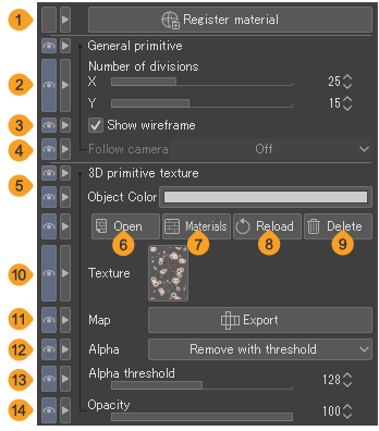
(1)Register material
The selected 3D primitive can be registered as a material.
(2)Number of divisions
The number of polygon divisions for each direction on 3D primitives for the X, Y, and Z dimensions. Only X and Y can be changed when a sphere or plane is selected.
To change the shape of the 3D object, adjust the X value for polygons and pyramids, and the X and Y values for spheres.
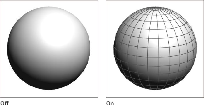
(3)Show wireframe
When turned on, the wireframe will be shown.
(4)Follow camera
This can be set when 3D primitive plane or polygon is selected. You can choose how to follow the camera when it changes position.
If you select Do not follow, it will rotate according to the camera position like a normal 3D material. When Follow is selected, the 3D primitive rotates to face forward according to the rotation of the camera.If you select Only horizontal, the 3D primitive rotates to face forward only when the camera is rotated horizontally.
(5)3D primitive texture
Allows you to set the texture and color of the primitive. To select the color, tap the color icon in Object Color to open the Color settings dialog.
(6)Open
In the Open dialog, you can import another file to use as a texture for the 3D primitive. You can import the following image file formats: Clip Studio format (extension: clip), BMP, JPEG, PNG, TIFF, Targa, Adobe Photoshop Document (extension: psd), and Adobe Photoshop Big Document format (extension: psb).
(7)Materials
In the Add a texture dialog, you can import an image material from the Material palette as a texture for the 3D primitive. For details on the Add a texture dialog, see "Adding a texture".
Memo | Dragging and dropping an image material onto a 3D primitive will also apply the image material as a texture for the 3D primitive. |
(8)Reload
When an external file is used as the 3D primitive texture, you can update the image to reflect any changes to the original file, based on the stored file path.
(9)Delete
Deletes the texture from the 3D primitive.
(10)Texture
A thumbnail of the current 3D primitive texture. You can tap the thumbnail to open the dialog and select a different file to import as a texture.
(11)Map
You can export the 3D primitive as a map in Clip Studio format (extension: clip). The exported map is divided into a “map” layer with grid lines, a “texture” layer with the texture image, and a “background color” layer filled with white. All are raster layers.
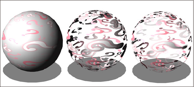
(12)Alpha
Sets how transparent areas of colors and textures are set on 3D primitives. Polygon lines are unaffected.
Opaque: The rendered portion of the texture appears opaque regardless of the actual opacity. Transparent parts of the texture will reveal the color of the 3D primitive.
Remove with threshold: Alpha threshold allows you to specify the area to be made transparent. If the alpha value is greater than Alpha threshold, the image will be opaque; if the alpha value is less, the image will be transparent.
Semi-transparent: Applies the color and texture opacity to the 3D primitive.
(13)Alpha threshold
You can specify the threshold for determining the transparent or opaque parts of the texture with an alpha value (265 levels). This setting is available when you set Alpha threshold to Remove with threshold.
(14)Opacity
Sets the color and texture opacity of 3D primitives by percentage. You can set this when Remove with Threshold or Semi-transparent is selected from Alpha.