C
Learn about Camera, Color Jitter, Closed Area Fill, and other setting categories starting with C in Clip Studio Paint.
Camera
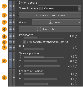
You can change and manage the camera angles when a 3D layer or 3D material is selected with the Object sub tool.
Memo | Some settings are unavailable when a Ver. 1.5 compatible 3D layer is selected. |
(1)Current camera
Tap to select and manage camera angles from the pull-down menu.
(2)Duplicate current camera
Tap this to duplicate the camera angle that is selected as Current camera.
(3)Angle
Tap Preset to see a list of default setting camera angles you can select. Some 3D materials may have a preset camera angle list.
(4)Center object
Tap to move the camera so that the selected 3D material is displayed in the center. If you have selected a specific part of a 3D drawing figure or 3D material, then it will be centered on the selected part.
(5)Projection method
You can change the projection method of the 3D camera to Perspective Projection or Parallel Projection.
Perspective Projection displays the 3D materials in perspective, so the size depends on the distance to the camera.
Parallel Projection does not display objects with true perspective, so the size is not affected by the distance from the camera. This is suitable for techniques such as isometric art, where there is no vanishing point.
(6)Perspective
Adds perspective to the 3D material. The larger the value set by the slider, the wider the angle of view. A smaller value results in a smaller angle of view. You can adjust this setting when the Projection method is set to Perspective Projection.
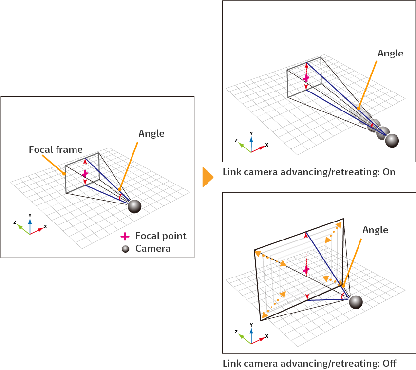
(7)Link camera advancing/retreating
When turned on, this links camera movements when adjusting the perspective. The focal point and focal frame remain fixed.
When turned off, with the camera position fixed, only the angle of view of the canvas camera changes even when the perspective is adjusted. You can adjust this setting when the Projection method is set to Perspective Projection.
Memo | In EX, you can check the position of the camera and focal point with the All sides view palette. |
(8)Projection scale
Set the field of view of the camera. The larger the value set by the slider, the wider the angle of view. You can adjust this setting when the Projection method is set to Parallel Projection.
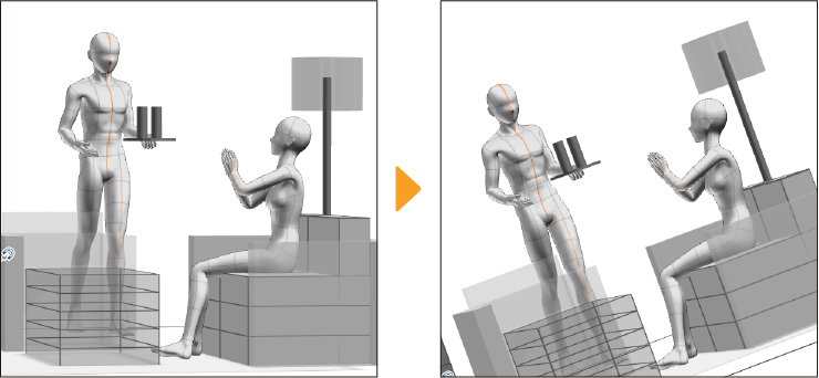
(9)Roll
Set the camera’s rotation angle while the camera position is fixed.
(10)Camera position
Adjust the X, Y, and Z sliders to move the camera position around the focal point.
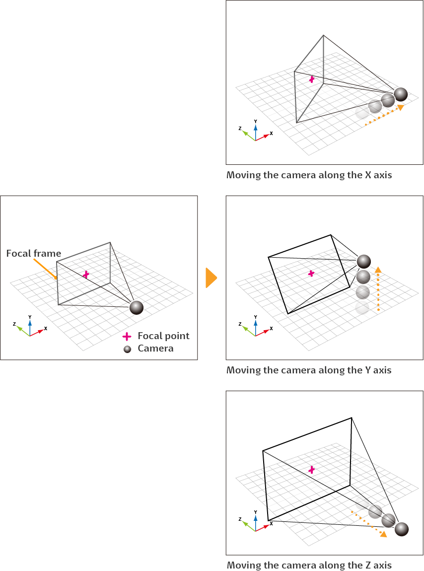
(11)Focal point position
Adjust the X, Y, and Z sliders to move the focal point position without moving the camera position.
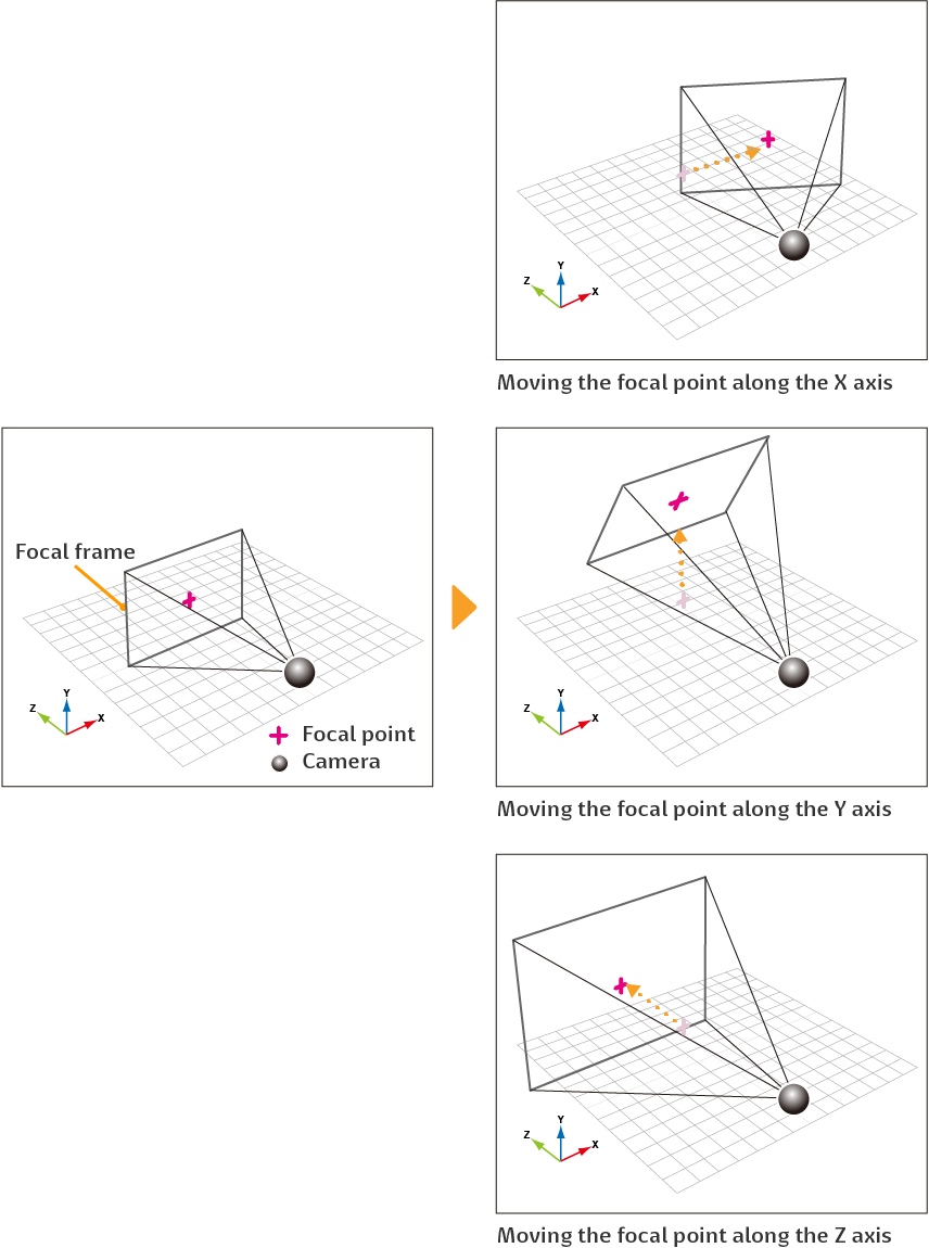
(12)Adapt view to object
When turned on, the position of the camera focal point will change to match the 3D material selected on the canvas. If a 3D material is selected from the Object list, the position of the focal point will not change.
If you select a specific part of the a 3D material, the focal point will change according to the position of the part.
Character
When a 3D character material is selected with the Object sub tool, you can use these settings to change its appearance.
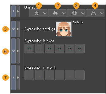
Memo | ·Depending on the version the 3D character was made in certain settings will not be available. ·You can perform the same operations in the Object Launcher for 3D characters as in the Character category. |
(1)Face
Tap this to see a list of faces you can select for the 3D character material.
(2)Hairstyle
Tap this to see a list of hairstyles you can select for the 3D character material.
(3)Body
Tap this to see a list of bodies you can select for the 3D character material. You can use this setting to change the character’s clothes.

(4)Accessories
Tap this to see a list of accessories you can select for the 3D character material. Use accessories to change hairstyles and add parts like bows to your 3D character. You can select and add multiple accessories.

(5)Expression settings
Tap this to see a list of facial expressions you can select for the 3D character material.
(6)Expression in eyes
For the chosen expression, you can adjust details like eyes being open or closed and the direction of the iris. Tap each button to apply the eye expression to the 3D character material.
(7)Expression in mouth
For the chosen expression, you can adjust details like the mouth being open or closed. Tap each button to apply the mouth expression to the 3D character material.
Circular text
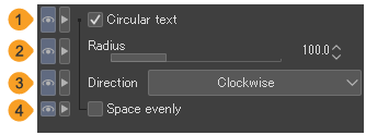
You can access circular text settings from the Text tool and Object tool when text is selected.
 p
p
(1)Circular text
Check the box to arrange text in a circular shape. When text is circular, text that overflows to a second line and superscript text will not be visible.
(2)Radius
Adjust the size of the circle using the slider or entering a number. A bigger number creates a bigger circle.
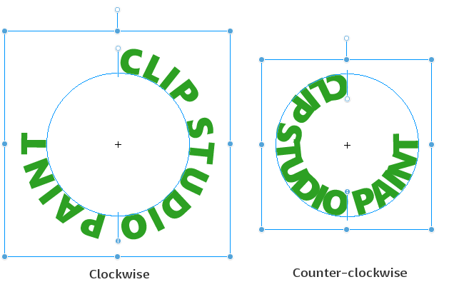
(3)Direction
Specify the direction of the writing. When set to Counter-clockwise, the text will be inside the circle.
(4)Space evenly
When turned on, the characters and spaces will be spaced evenly between the start and end points. For details on the start and end points, see "Aligning text on a circle".
Closed area fill
You can make detailed settings for how to fill when using the Enclose and fill and Paint unfilled area sub tools. The same settings can be made with the Shrink selection sub tool under the Selection area tool.
The Closed area fill category of the Fill and Selection area tools have the same settings, but the results are different. The following describes each item using the Fill tool as an example.
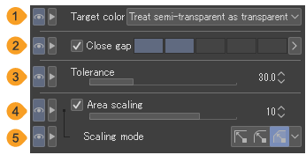
(1)Target color
Sets the target color to be filled. For details, see "Target color".
(2)Close gap
When turned on, if there are gaps in the area you want to fill, the fill will still stop at the gaps without spilling from the area. Use the indicator to specify the size that is interpreted as a gap in the lines.
(3)Tolerance
You can adjust the error margin of color for filling. The larger the value, the larger the tolerance to include areas of colors different to the tapped color.
(4)Area scaling
When turned on, you can enlarge or shrink the original area by the amount of pixels specified by the slider.
(5)Scaling mode
When Area scaling is turned on, you can sets the corner shape of the area to Round, Rectangle, or To darkest pixel. For details, see "Fill".
Color Jitter
You can randomize the hue, saturation, and color of the drawing color as you draw, or make the color change depending on pen pressure and brushstroke speed.
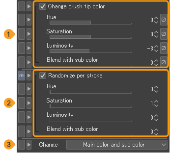
(1)Change brush tip color
Turn this on to change the hue, saturation, brightness, and level of color mixing with the sub drawing color.
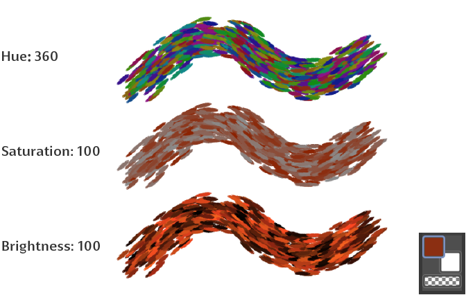
Blend with sub color allows you to draw with a color made from the main drawing color and sub drawing color. The larger the value, the higher the ratio of the sub drawing color. Tap the Dynamics icons to make the colors reflect changes in the pen pressure and brushstroke speed.
(2)Randomize per stroke
Turn this on to change the hue, saturation, brightness, and color mixing with the sub drawing color with each brushstroke. Make the values higher in these settings for more dramatic color changes.
(3)Change target
If you are using a brush tip shape that uses both the main and sub drawing color or if you have Blend with sub color turned on, you can specify whether to apply Change brush tip color or Randomize per stroke hue, saturation, and brightness to the Main color and sub color, Main color, or Sub color.
Compatibility
This category is available when the Text tool is selected or when a text layer is selected with the Object sub tool. You can set the version for which the text is created from the Version menu. This setting may affect the way the text is created.
If you select a newer version, the text will reflect the latest features and settings, but if you open the Clip Studio format file in an older version of Clip Studio Paint, text editing may be locked. If you select an older version for the compatibility setting, you can edit the text in earlier versions of Clip Studio Paint.
Continuous curve
You can adjust settings for drawing continuous curves with the Polyline, Continuous curve, and Bezier curve sub tools of the Figure tool.
The Continuous curve category can also be set for sub tools that draw lines and curves, such as the Figure tool > Focus lines and Speed lines sub tools, the Ruler > Curved ruler sub tool, and the Selection area > Polyline selection sub tool.
The available settings differ depending on the selected tool.
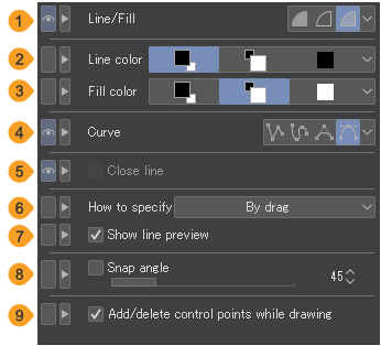
(1)Line/Fill
You can choose how to draw continuous curves from Create fill, Create line, and Create both line and fill. This appears when using the Continuous curve sub tool.
Create fill | When you draw a continuous curve or polygonal line, a closed shape is created by connecting the start and end points, and the area is filled with the drawing color. There is no outline. |
Create line | The continuous curve or polygonal lines are drawn in the drawing color. The shape can be drawn as you want it. |
Create both line and fill | When you draw a continuous curve or polygonal line, a closed shape is created by connecting the start and end points, and the area is filled. You can set the line color and the fill color. |
(2)Line color
When Line/Fill is set to Create both line and fill, you can set the outline color of the continuous curve to Main color, Sub color, User color, or Select user color. This appears when using the Continuous curve sub tool.
Main color | Tap to use the current main drawing color. |
Sub color | Tap to use the sub drawing color. |
User color | Tap to use the specified color. Tap again to use the current main drawing color as the specified color. Unlike Main color, the specified color will be used even if the main drawing color is changed with a color palette. |
Select user color | You can specify the user color from the Color settings dialog. There is not a button for this setting. You can select it from the menu that appears when you tap the rightmost button. |
(3)Fill color
When Line/Fill is set to Create both line and fill, you can set the color of the area that will be filled to Main color, Sub color, User color, or Select user color. The settings are the same as the line color. This appears when using the Continuous curve sub tool.
(4)Curve
You can select how to draw curves from Straight line, Spline, Quadratic Bezier, and Cubic Bezier. For details on how to draw each curve, see "Straight lines", "Curved lines", and "Complex lines".
Note that you cannot select Cubic Bezier from the sub tools under the Focus lines and Speed lines groups in the Figure tool.
(5)Close line
When turned on, you can connect the start and end points to create a closed line. This setting can be used when the Continuous curve sub tool’s Line/Fill setting is set to Create line.
(6)How to specify
When drawing a cubic Bezier curve, you can set the control point specification method to By click or By drag. For details on how to draw with each setting, see "Cubic Bezier curves".
(7)Show line preview
Turn on to display the curve up to the mouse cursor. This is a preview of the line drawn if you tap at the current position. The preview is updated according to the mouse cursor’s position. When using a tablet, the line preview can only be shown when drawing with a mouse.
This can be set when By drag is selected from How to specify.
(8)Snap angle
When creating a polyline or continuous curve, you can move the pen or mouse at set angle increments.
(9)Add/delete control points while drawing
Turn this on so you can add or delete control points while creating a polyline or continuous curve. Tap a control point to remove it from the line. Tap on the line you are drawing to add control points.
Control point
This setting is available when the Correct line tool > Control point sub tool is selected.
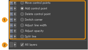
(1)Process
For details on each setting, see "Control point".
(2)All layers
When turned on, the selected process can be applied to vector layers, balloon layers, frame border folders, and drawn lines on rulers on the canvas. Tap the line you wish to edit to switch to that layer.
Copy stamp
Allows you to set how the image is referenced when using the Copy stamp sub tool.

(1)Adjust reference position each time
Turn this on to adjust the reference position in relation to the reference image when drawing. Even if you change the stroke there will be no change in position relative to the reference point. When turned off, you can draw by referring to the first reference point each time the stroke changes.
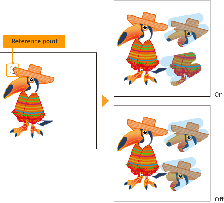
(2)Mode for specifying reference position
When turned on, the mode changes to reference point specification mode, where the tapped point becomes the new reference point. When drawing, turn off Mode for specifying reference position. You will not be able to draw if it is turned on.
Even if this setting is turned off, you can hold Alt while tapping on the canvas to set a new reference point.
Correction
You can make settings for correcting pen touch when drawing lines.
The Correction category can be used for a variety of tools, including drawing tools such as the Pen and Liquify tools, and tools for drawing shapes such as the Figure, Balloon, and Frame Border tools. The available settings differ depending on the selected tool.
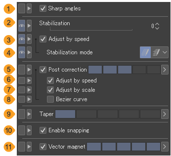
(1)Sharp angles
When turned on, angles drawn in the line will become pointed.
(2)Stabilization
Sets the stabilization for tablets. Larger values produce smoother lines, while smaller values produce lines that are truer to the stroke.
(3)Adjust by speed
When turned on, the speed of the pen affects how stabilization is applied.
(4)Stabilization mode
When Adjust stabilization by speed is turned on, you can choose a stabilization mode.
Increase stabilization when drawing slowly | Increases stabilization the slower the pen moves. This stabilizes small shakes when drawing slowly. However, if the Stabilization value is set to 30 or higher, the setting will be disabled. |
Reduce stabilization when drawing quickly | Decreases stabilization the faster the pen moves. This will fix lagging lines. |
(5)Post correction
When on, this corrects lines after they are drawn. Smooths the line after it is stabilized. You can set the strength of Post correction with the indicator or a numerical value.
When drawing on a vector layer, the higher the value of Post correction, the fewer the number of control points.
(6)Adjust by speed
Adjusts the strength of Post correction by the speed of the stroke. This setting can be adjusted when Post correction is turned on.
(7)Adjust by scale
Adjusts the strength of Post correction by the display ratio of the canvas. This setting can be adjusted when Post correction is turned on.
(8)Bezier curve
This changes how curves are corrected in post. When turned on, lines become quadratic Bezier curves after correction. When turned off, lines become spline curves after correction.
If you draw on a vector layer or draw a line with control points using the Balloon or other tools, you can see how the curve is processed.
(9)Taper
Changes the length by which a line is continued when drawn by gradually decreasing the pen pressure.
When the value is large, the line follows the pen by becoming thinner even after the pen is released from the tablet as if it were drawn with a brush with long tip.
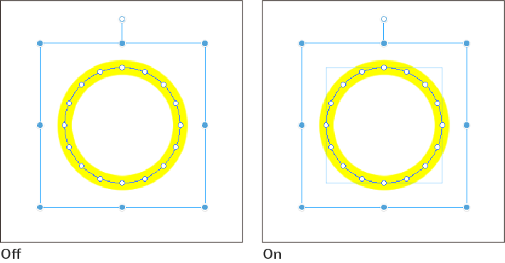
(10)Enable snapping
When on, you can draw while snapping as set up in the View menu > Snap. You can snap to items like rulers, objects, and control points.
If you select a vector layer, balloon layer, frame layer, text layer, or ruler with the Object tool when Enable snapping is turned on, snapping lines will appear inside the bounding box. These lines will be the snapping point when snapping to other objects.
(11)Vector magnet
When turned on, you can draw by snapping to previously drawn lines when drawing on a vector layer. Some line types are merged into a single line. The indicator allows you to adjust the strength of the snap. The larger the value, the more distant lines will snap together.
(12)Snap to default border
When turned on, shapes and other objects can be drawn so that they snap to a default border or to a standard size. For animation projects, it snaps to the drawing frame. This can be set when selecting a sub tool for drawing shapes, such as the Figure or the Frame Border tools.
Memo | Enable snapping, Vector magnet, and Snap to default border are not available in Clip Studio Paint DEBUT. |
Create balloon
When creating a balloon using a Balloon sub tool, you can set the color of the balloon and how the layer will be created.
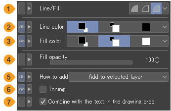
(1)Line/Fill
You can choose how to draw the balloon from Create fill, Create line, and Create both line and fill.
·Create Fill draws a balloon by filling it with the drawing color. The shape will not have an outline.
·Create line draws the outline of the balloon with Line color.
·Create both line and fill draws the outline of the balloon with Line color and fills the inside of the balloon with Fill color. You can set both Line color and Fill color.
(2)Line color
When Line/Fill is set to Create both line and fill, you can set the outline color of the balloon to Main color, Sub color, User color, or Select user color.
Main color | Tap to use the current main drawing color. |
Sub color | Tap to use the sub drawing color. |
User color | Tap to use the specified color. Tap again to use the current main drawing color as the specified color.Unlike Main color, the specified color will be used even if the main drawing color is changed with a color palette. |
Select user color | You can specify the user color from the Color settings dialog. There is not a button for this setting.You can select it from the menu that appears when you tap the rightmost button. |
(3)Fill color
When Line/Fill is set to Create both line and fill, you can set the fill color of the balloon to Main color, Sub color, User color, or Select user color. The settings are the same as the line color.
(4)Fill opacity
Sets the opacity for the balloon.
(5)How to add
You can set how balloon layers are added when creating a balloon. If you tap Create new layer, a balloon layer is created on the Layer palette when the balloon is created.
If you tap Add to selected layer and a balloon layer is selected, the balloon is added to the selected layer. If any other layer type is selected, a new balloon layer will be created.
(6)Toning
When turned on, you can create a toned balloon layer. When tone is applied, the expression color of the balloon layer becomes gray, and the drawing colors become black and white.
If turned off, the image will match the Basic expression color of the canvas. For details on expression colors, see "Expression Colors and Drawing Colors".
(7)Combine with the text in the drawing area
When turned on, if you draw a balloon over text, the balloon will be created on the same layer as the text. Even if How to add is set to Create new layer, the Combine with the text in the drawing area setting takes precedence.
Create frame
These settings can be found with the Frame border tool > Create frame sub tools.
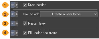
(1)Draw border
Turn this on to draw a border line when making a frame.
(2)How to add
You can change the way that frames get added to the frame border folder. Select Create a new folder to create a new frame border folder when creating a frame.Select Add to selected folder to add the frame to the selected frame border folder when selecting that folder or a layer within the folder.If any other layer type is selected, a new frame border folder will be created.
(3)Raster layer
When turned on, a raster layer is created in the frame border folder when you make a new frame border folder.
(4)Fill inside the frame
When turned on, a white fill layer is created in the frame border folder when you make a new frame border folder.
Create ruler
These are settings for how to create rulers and for the scale when creating a ruler with the Ruler tool.

(1)Create at editing layer
When turned on, the ruler is created on the selected layer. When turned off, a new raster layer is created at the bottom of the layer palette when you make a new ruler.
(2)Scale
When turned on, a scale is displayed on the selected ruler. This is the same as the Ruler setting.
(3)Number of divisions
When Scale is set to Equal division, you can set the number of divisions.
Create special ruler
You can set the type and creation method of special rulers when the Special ruler sub tool or Guide sub tool.
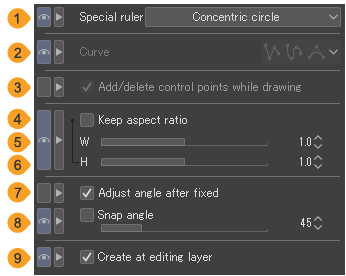
(1)Special ruler
Select the type of ruler to create. You can choose from Parallel line, Parallel curve, Multiple curve, Radial line, Concentric circle, or Guide.
(2)Curve
Set how to draw the ruler. You can select from Straight line, Spline, Quadratic Bezier, or Cubic Bezier. For how to draw straight lines, see the "Straight lines".
This can be set when Parallel curve line, Multiple curve, or Radial curve is selected in Special ruler.
(3)Add/delete control points while drawing
Turn this on so you can add direction points or to delete control points while drawing the line for the ruler. Tap a control point to remove it from the line.Tap on the line you are drawing to add control points.
This can be set when Parallel curve line, Multiple curve, or Radial curve is selected in Special ruler.
(4)Keep aspect ratio
When turned on, you can create a concentric circle ruler with a set aspect ratio.
(5)Width (W)
When Keep aspect ratio is turned on, you can set the horizontal ratio of the concentric circle ruler with a slider or numerical values.
(6)Height (H)
When Keep aspect ratio is turned on, you can set the vertical ratio of the concentric circle ruler with a slider or numerical values.
(7)Adjust angle after fixed
When turned on, after dragging and releasing to draw a concentric circle ruler, you can drag again to adjust the angle of the ruler. Tap to confirm the angle of the concentric circle ruler.
When using a mouse, you can adjust the angle after drawing the concentric circle ruler by simply moving the mouse, without pressing the mouse button. Click to confirm the angle of the concentric circle ruler.
(8)Snap angle
When creating or rotating a ruler, you can draw it at the set angle increments.
This also applies when adjusting the angle of a concentric circle ruler with the Adjust angle after fixed setting.
You can also use this angle when drawing special rulers other than radial line rulers or guide lines.
(9)Create at editing layer
When turned on, the ruler is created on the current layer. When turned off, a new raster layer is created when you make a new ruler.
Memo | If creating a Special ruler > Guide when there is already a layer named “Guide", the guide will be created on that layer. |
Create symmetrical ruler
With these settings, you can set the number of the lines of a symmetrical ruler and the type of symmetry when using the Symmetrical ruler sub tool.
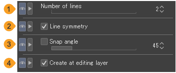
(1)Number of lines
Configures the number of lines which can be drawn at once when snapping to the symmetrical ruler.
(2)Line symmetry
When turned on, you can create a ruler with line (mirror) symmetry. When turned off, you can create a ruler with rotational symmetry.You cannot use line symmetry if there is an odd number of lines for the ruler.
(3)Snap angle
When turned on, you can specify the angle of the ruler.
(4)Create at editing layer
When turned on, the ruler is created on the current layer. When turned off, a new raster layer is created when you make a new ruler.
Cut border
You can use these settings to set how to divide frame borders when using sub tools in the Frame Border tool > Cut border group.
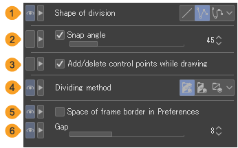
(1)Shape of division
You can choose the type of line that will divide the frames: Straight line, Polyline, or Spline.

(2)Snap angle
When dividing frames, you can move the pen or mouse at set angle increments.
(3)Add/delete control points while drawing
Turn this on so you can add or delete control points while dividing the frame border. Tap a control point to remove it from the line.Tap on the line you are drawing to add control points.
This can be set when Divide by polyline or Divide by spline is selected from Shape of division.
(4)Dividing method
Sets how to divide the layer folder when the frame border is divided.
Divide frame folder and duplicate inside layer | Creates a new frame border folder for each divided frame border. Each frame border folder includes a copy of the layer inside the frame border folder before being divided. |
Divide frame folder and create empty folder | Creates a new frame border folder for each divided frame border. |
Divide not folder but frame border | You can split frames within the same frame border folder. Does not create a new frame border folder or raster layer when dividing a frame border. |
(5)Space of frame border in Preferences
When turned on, this divides by spacing the border lines by the value set in Frame border under Ruler/Unit on the Preferences dialog.
(6)Gap
You can specify the width of the gap (gutter) with the slider.
This setting is available when Shape of division is set to Divide by polyline or Divide by spline.
When the Shape of division is set to Straight line is selected, you can set the horizontal and vertical gutters. Horizontal gutter is the space between upper and lower frames.Vertical gutter is the space between left and right frames.
If Space of frame border in Preferences is turned on, you cannot change the Gap, Horizontal gutter, or Vertical gutter settings.